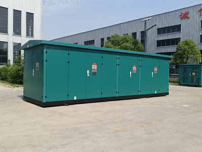
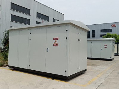
Photovoltaic power storage box substation
Product description
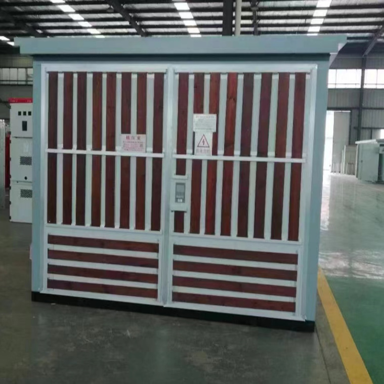
With the development of society, people's demand for electricity is increasing, but the power shortage during the day may lead to excess power at night, in order to avoid this model, we must try to avoid this situation as much as possible. So the energy storage box substation was born.
In order to overcome the shortcomings of existing technology, through the combination of substation and energy storage system, energy storage can be realized at night when electricity consumption is low, and discharge is carried out during daytime power peaks, and the peak-valley price difference is used to reduce the burden of enterprises while ensuring power demand during power peaks, and energy storage box-type substations can also be used as emergency power supplies.
The technical scheme of energy storage box substation is: an energy storage box substation, including a substation system and an energy storage system, wherein: the energy storage system is disposed in the energy storage box, the substation system is disposed inside the substation box, and the low-voltage load end of the substation system is electrically connected to the charging end of the energy storage system, the energy storage system includes a battery pack, a low-voltage switchgear and a discharge end, the charging end and the discharge end are electrically connected to the battery pack through the low-voltage switchgear, and the discharge end is electrically connected to the DC charging equipment and the low-voltage load end of the substation system, The DC charging equipment is installed on the outer wall of the energy storage box.
The low-voltage switchgear is provided with a dual power supply switching device, a timer one and a timer two, the charging end is electrically connected to the second input end of the dual power supply switching device and the input end of timer one, the output end of timer one is electrically connected to the battery pack through the UPS power supply, the battery pack is electrically connected to the first input end of the dual power supply switching device through the UPS power supply and timer two, and the output end of the dual power supply switching device is electrically connected to the discharge end.
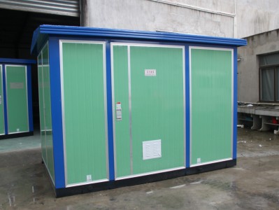
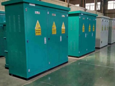
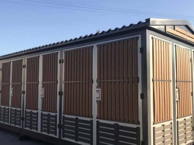
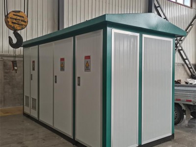
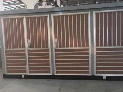
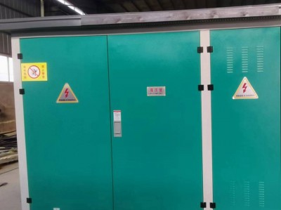
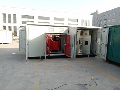
Substation systems include transformers and/or solar power generation equipment and/or wind power generation equipment. The energy storage box and the substation box are integrated structures or split structures. Both the energy storage box and the substation box are equipped with lifting rings and opening and closing doors. DC charging equipment is DC charging pile.
The beneficial effects of the utility model are:
Through the combination of substation and energy storage system, the energy storage box-type substation realizes energy storage at night when electricity consumption is low, and discharge during daytime power peaks, using peak-valley price difference to reduce the burden of enterprises while ensuring power demand during power peaks, and can also be used as an emergency power supply to improve the quality of electricity.
The energy storage system of the present invention is disposed in the energy storage box, the substation system is disposed in the substation box body and/or the top of the energy storage box, and the low-voltage load end of the substation system is electrically connected to the charging end of the energy storage system, the charging end of the energy storage system is electrically connected with the DC charging equipment and the low-voltage load end of the substation system, through the role of energy storage, energy storage is realized at night when electricity consumption is low, and discharge during the daytime power spike to power the same load, at the same time, the substation system is set in the substation box / or the top of the energy storage box, It can be specifically set according to the actual situation of the substation system to adapt to different substation systems.
The energy storage box and the substation box of the utility model are integrated structures or split structures, and the substation system is a transformer and/or solar power generation equipment and/or wind power generation equipment, which can be combined according to different substation systems to improve adaptability.
The charging end of the new energy storage system is electrically connected to the DC charging pile set on the outer wall of the energy storage box, which can use the stored low-valley electric energy to supply power to DC power equipment at any time at each time, and reduce electricity costs by taking advantage of the peak-valley electricity price difference.
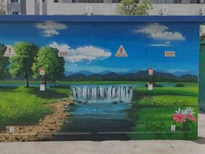
The new energy storage box and substation box are equipped with lifting rings and opening and closing doors, which are convenient for hoisting transfer and equipment maintenance, and at the same time, warning signs are set on the box to ensure the safety of power supply.
In the low-voltage switchgear of the utility model, the charging end is electrically connected to the second input end of the dual power switching device and the input end of timer one, the output end of timer one is electrically connected to the battery pack through the UPS power supply, the battery pack is electrically connected to the first input end of the dual power supply switching device through the UPS power supply and timer two, and the output end of the dual power switching device is electrically connected to the discharge end, and the battery pack and the charging end are electrically connected through the timer one to realize the charging battery at night when the power is low, Through the timer 2 to realize the electrical connection between the battery and the dual power switching device, discharge during the daytime peak power consumption, supply power to the load, use the principle of peak shaving and valley filling to ensure the stability of power supply of the power grid, and use the peak-valley difference to reduce the cost of electricity.
The charging end of the utility model is electrically connected to the second input end of the dual power switching device and the input end of the timer one, the output end of the dual power switching device is electrically connected with the discharge end, so that the charging end is directly connected to the discharge end through the dual power supply switching device, when the UPS power supply detects that the battery power reaches the set value, the first input end of the dual power switching device is disconnected, the second input end of the dual power switching device is closed, and the power supply is directly supplied through the substation system to ensure the stability of the power supply.
The energy storage system of the utility model can be used as an emergency (backup) power supply, in the event of a power failure or a failure of the power transformation system, emergency power supply through the energy storage system to ensure the stability of the user's production process and improve the power quality.

