
Chint current transformer Class 0.5 5VA/3.75VA
Product description

Chint current transformer Class 0.5 5VA/3.75VA is a high-precision measuring device suitable for low-voltage AC circuits, mainly used in scenarios such as current monitoring and electric energy metering in power systems. The following is a detailed analysis of key parameters and application points:
I. Core Technical Parameters
1. **Accuracy Class (Class 0.5)**
It indicates that the measurement error of the transformer does not exceed ±0.5%, which complies with the GB/T 20840 standard. It is suitable for metering and measurement scenarios with high precision requirements, such as industrial electricity billing and current monitoring of precision equipment. The Class 0.5 accuracy can maintain stable performance under light loads (e.g., 10% of the rated current) without the need for additional S-class design.
2. Rated Output (5VA/3.75VA)**
- **Application Differences**: If the secondary circuit includes long-distance wires or multiple instruments, 5VA should be preferred to avoid accuracy degradation caused by excessive load.
3. **Current Ratio and Ratio Range**
This model usually supports multiple current ratios (such as 100/5A, 150/5A, etc.), and the ratio can be adjusted through the number of穿心 turns. For example, when a 150/5A transformer is穿1 turn, the ratio is 30:1; when穿2 turns, the ratio is 15:1. The selection of the ratio should match the actual primary current, and it is recommended that the working current be 60%-80% of the rated value to optimize accuracy.
II. Application Scenarios and Selection Suggestions
1. **Typical Applications**
- **Electric Energy Metering**: Used with three-phase four-wire energy meters (such as DT862-4 type) to ensure the accuracy of electricity fee settlement.
- **Industrial Monitoring**: Connected to ammeters, power meters and other equipment to monitor the current of loads such as motors and transformers in real time.
- **Protection Linkage**: Cooperate with relays or smart meters to realize overcurrent protection or data remote transmission.
2. **Key Steps for Selection**
- **Case Reference**:
If the secondary circuit includes 3 ammeters (each 0.05Ω) and 20 meters of 4mm² copper wires (with a resistance of about 0.09Ω), the total load is \( 0.05\times3 + 0.09 + 0.1 = 0.34\Omega \). In this case, choosing 5VA (0.2Ω) may exceed the limit, so it is recommended to use the 3.75VA version or increase the cross-sectional area of the wire.
3. **Installation and Environmental Requirements**
- **Physical Installation**: Adopt base plate fixing or busbar clamping method, and select the through-core aperture according to the cable diameter (such as φ30mm, φ50mm).
- **Environmental Conditions**:
- Temperature: -5℃~40℃, Humidity: 24-hour average ≤95%, Altitude: ≤1000 meters.
- Avoid installation in areas with corrosive gases or strong electromagnetic interference.
III. Usage Precautions
1. **Wiring Specifications**
- The secondary circuit must be closed, and open-circuit operation is strictly prohibited, otherwise high voltage may be generated, endangering safety.
- Use copper wires with a cross-sectional area of ≥2.5mm² to ensure low-impedance transmission.
- The S2 terminal must be reliably grounded to prevent the accumulation of induced voltage.
2. **Load Matching and Calibration**
- Regularly check whether the secondary load is within the rated range (25%-100%) to avoid core saturation caused by long-term overload.
- If the load changes greatly (such as frequency converter-driven equipment), a wide-range transformer (such as Class 0.5SS) can be selected to cover 0.1%-200% of the rated current.
3. **Maintenance and Replacement**
- Check the appearance of the transformer for cracks, discoloration or signs of overheating every year, and replace aging components in time.
- After long-term operation, it is recommended to calibrate the accuracy through a standard source to ensure that the error is within the allowable range.
The accuracy class of current transformers is a core indicator to measure their measurement accuracy, which directly determines the degree of agreement between the secondary side output current and the primary side actual current, and has a key impact on the **accuracy, stability and application scenario adaptability** of the measurement results. The specific impact can be analyzed from three dimensions: the nature of errors, accuracy requirements in different scenarios, and actual measurement deviations:
I. The Nature of Accuracy Class: Hard Regulations on Error Range
The accuracy class of current transformers (such as Class 0.1, Class 0.2, Class 0.5, Class 1, etc.) is defined by national standards (such as GB/T 20840), which essentially limits the maximum allowable values of **ratio error** and **phase error**:
For example, a Class 0.5 transformer has a ratio error not exceeding ±0.5% at rated current; a Class 1 transformer has a ratio error not exceeding ±1%.
- **Phase Error**: The phase difference between the secondary current and the primary current (in minutes), which mainly affects the measurement involving phase, such as power and electric energy (active power calculation requires the current and voltage to be in the same phase). The higher the accuracy class, the smaller the phase error (for example, the phase error of Class 0.2 is usually ≤10′, and that of Class 0.5 is ≤30′).
II. Specific Impact on Measurement Results
1. Directly Lead to Absolute Deviation of Measurement Values
The accuracy class determines the maximum deviation range between the measurement result and the true value. Taking "the actual current on the primary side is 100A, and the transformation ratio is 100/5A (secondary rated current 5A)" as an example:
- Class 0.5 transformer: The allowable deviation of the secondary side measurement current is ±0.5%×5A = ±0.025A, and the corresponding primary side calculation deviation is ±0.025A×20 = ±0.5A (that is, the measurement value is between 99.5A and 100.5A).
- Class 1 transformer: The secondary deviation is ±0.05A, and the primary side deviation is ±1A (the measurement value is between 99A and 101A).
It can be seen that the lower the accuracy class, the greater the deviation between the measured value and the true value, which may lead to misjudgment of the load current (such as misjudging whether the motor is overloaded).
2. Affect the Measurement Reliability in Different Scenarios
Different application scenarios have significantly different sensitivities to accuracy, and mismatched accuracy classes may lead to serious consequences:
- **Electric Energy Metering Scenarios** (such as electricity fee settlement):
High accuracy classes (Class 0.2 or Class 0.5) are required, otherwise long-term accumulated errors will lead to economic losses. For example, if the total primary side current in a month is 10⁶A·h, the maximum cumulative error of a Class 0.5 transformer is ±5000A·h (calculated at 0.5%). If the electricity price is 0.5 yuan/A·h, it may lead to a cost deviation of ±2500 yuan; while the deviation of a Class 1 transformer will expand to ±10000A·h (±5000 yuan).
- **Industrial Monitoring Scenarios** (such as motor current monitoring):
Medium accuracy (Class 0.5 or Class 1) can meet the requirements, and a deviation within ±1% usually does not affect the judgment of the equipment operating status (such as whether the motor is operating within the rated current range).
- **Protection Scenarios** (such as overcurrent protection):
The requirement for accuracy is low (Class 3 or Class 5), and more attention is paid to the response speed under large currents, allowing large errors (as long as the protection can be triggered).
3. Differences in Accuracy Performance Under Light Loads (Specialty of S Class)
The error limit of ordinary accuracy classes (such as Class 0.5) is only valid within the range of **50%~100% of the rated current**. If the actual current is lower than 20% of the rated value (light load), the error will increase significantly (may exceed 1%); while the class with "S" (such as Class 0.5S) is specially optimized for light load accuracy, and can maintain an error of ≤±0.5% within the range of 1%~120% of the rated current.
For example: A Class 0.5 transformer with a rated current of 100A, when the actual current is 10A (10% of the rated value), the error may reach ±2%; while the Class 0.5S can still control the error at ≤±0.5% at 10A. This is crucial for scenarios with large current fluctuations (such as lighting circuits and small motors), which can avoid serious distortion of measurement values under light loads.
III. Summary: Core Impact of Accuracy Class
The accuracy class of current transformers directly determines the deviation between the measurement result and the true value by limiting the range of **ratio error and phase error**:
- The smaller the class number (such as Class 0.1 < Class 0.2 < Class 0.5), the smaller the error, the more accurate the measurement, but the higher the cost;
- It is necessary to select the type according to the accuracy requirements of the application scenario: high classes (Class 0.2 and above) are preferred for metering scenarios, medium classes (Class 0.5) can be selected for monitoring scenarios, and low classes (Class 3 and below) can be selected for protection scenarios;
- Attention should be paid to the "S class" in light load scenarios to avoid error out of control of ordinary classes under light loads.
In short, the accuracy class is a key parameter to balance measurement accuracy and cost, and selecting an appropriate class can ensure the "credibility" of measurement results.
More recommendations
-
Schneider LC1E400 Contactor
-

Chint JQX13F Electromagnetic Relay
-
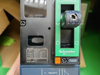
Schneider C16F2TM160 Circuit Breaker
-
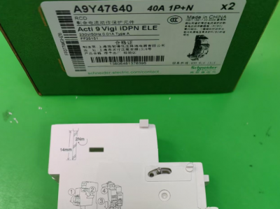
Schneider A9Y47640
-
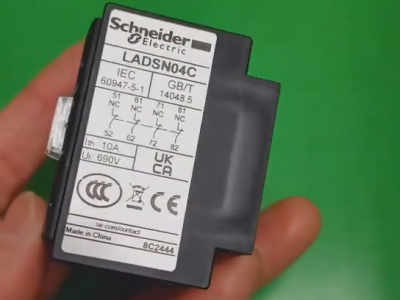
Schneider LADN04C
-
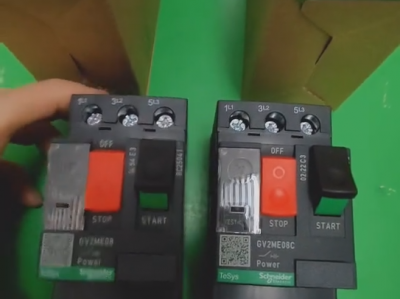
Schneider GV2ME08C motor circuit breaker
-
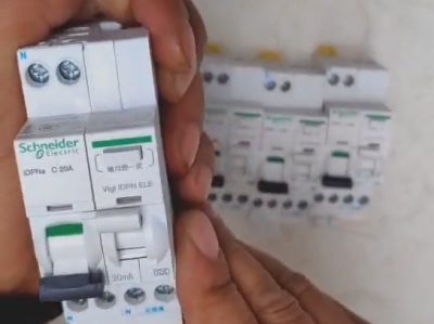
Schneider IDPNa C20A miniature circuit breaker (MCB)
-
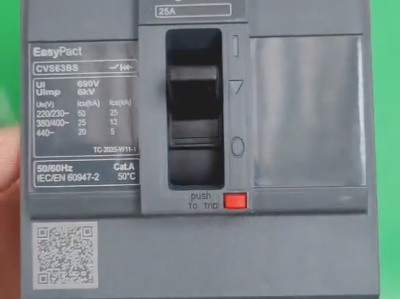
Schneider CVS63BS25A molded case circuit breaker (MCCB)
-
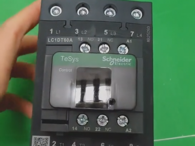
Schneider LC1DT80 4-pole contactors
-
Schneider Electric Circuit Breaker Model A9P28620

