
Chint moulded case circuit breaker NXM-63S/3300-32A
Product description

The Chint moulded case circuit breaker NXM-63S/3300-32A is an electrical product used for power distribution protection. The following is its detailed introduction:
Model Meaning**
- "NXM" indicates the product series is Chint NXM series moulded case circuit breaker.
- "63" represents the frame rated current is 63A, meaning the maximum rated current of the trip unit that can be installed in this circuit breaker is 63A.
- "S" denotes the breaking capacity, specifically the rated ultimate breaking capacity is 25kA.
- The first "3" indicates the number of poles: 3P (three poles), suitable for three-phase circuits.
- The second "3" indicates the trip unit type is thermal-magnetic, with both overload long-time delay and short-circuit instantaneous protection functions.
- "00" means no accessories.
- "32A" is the rated current of the circuit breaker, referring to the current value at which the circuit breaker can operate stably for a long time.
Main Performance Parameters**
- **Rated Insulation Voltage**: Up to 800V.
- **Rated Working Voltage**: Suitable for AC 50Hz, with a rated working voltage up to AC 690V.
- **Operation Mode**: Body operation.
- **Wiring Mode**: Front-mounted wiring.
Functional Features**
It features a small size, high breaking capacity, short arcing distance, etc. It can be used to distribute electrical energy and protect circuits and power equipment from damage caused by faults such as overload and short circuit. It can also be used for infrequent starting of motors and overload/short-circuit protection. It complies with standards such as GB/T 14048.2 and IEC 60947-2, and has obtained certifications such as CCC, KEMA, CB, and NOM.
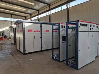
Application Scenarios**
Suitable for power distribution systems in power stations, factories, mines, modern high-rise buildings, and intelligent buildings. It plays a protective role in power distribution networks with AC 50Hz, a rated working voltage up to 690V, and a rated working current up to 63A and below.
The installation of Chint moulded case circuit breaker NXM-63S/3300-32A must follow standardized procedures to ensure safety and normal operation. The detailed installation method is as follows:
一、Preparations Before Installation**
1. **Check Product Integrity**
- Confirm that the circuit breaker has no external damage, and components (such as wiring terminals and operation handles) are complete, without looseness or missing parts.
- Verify whether the model and parameters (such as rated current 32A, number of poles 3P, etc.) are consistent with the design requirements.
2. **Environmental Requirements**
- The installation site should be dry, free of corrosive gases and severe vibrations, and the altitude should not exceed 2,000 meters.
- The ambient temperature should be within the range of -5°C to +40°C to avoid performance degradation in high or low temperatures.
3. **Tools and Materials Preparation**
- Prepare tools such as screwdrivers and wrenches, as well as wires of appropriate specifications (selected according to the load current), wiring terminals, etc.
Installation Steps**
1. Determine the Installation Position and Method**
- **Installation Direction**: The circuit breaker should be installed vertically (the operation handle is "on" when upward and "off" when downward). Avoid horizontal or inclined installation to prevent affecting the action of the tripping mechanism.
- **Installation Position**: Install it on the insulated base plate of the distribution box or switchboard, ensuring sufficient space around (it is recommended to reserve at least 50mm spacing on all sides) for heat dissipation and operation.
2. Fix the Circuit Breaker**
- Use the installation holes自带 (usually located on both sides of the housing) of the circuit breaker to fix it to the base plate with screws, ensuring firm installation to avoid poor contact caused by vibration.
3. Wiring Operation**
- **Distinguish Inlet and Outlet Ends**: The upper end of the circuit breaker is the inlet end (marked "L1/L2/L3" or "IN"), and the lower end is the outlet end (marked "T1/T2/T3" or "OUT"). Do not connect them reversely, as this may affect the protection function.
- **Conductor Connection**:
1. Strip the insulation layer of the conductor (the length is determined according to the depth of the terminal, generally 10-15mm), ensuring the conductor is free of damage or oxidation.
2. Insert the conductor into the wiring terminal and tighten the terminal screw with a screwdriver (with moderate force to avoid over-tightening that may damage the conductor or under-tightening that may cause heating).
3. The 3P circuit breaker needs to be connected to three-phase live wires (L1/L2/L3). If the neutral wire (N) needs to be connected, it should be connected through the neutral busbar in the distribution box (note that this model "3300" has no neutral terminal).
- **Precautions**:
- The conductor cross-sectional area should match the rated current (6-10mm² copper wire is recommended for 32A) to ensure sufficient current-carrying capacity.
- After wiring, check whether the terminals are firm and there are no exposed copper wires to avoid short-circuit risks.
4. Operation Handle Test**
- After installation, manually operate the handle for "on-off" testing to ensure flexible movement without jamming.
- The handle should be locked in the "on" position when closing and can be reliably disconnected when opening.
Safety Precautions**
1. **Power-off Operation**: Be sure to disconnect the upstream power supply before installation, and perform voltage testing to confirm no electricity before operation to avoid electric shock accidents.
2. **Grounding Protection**: The distribution box or switchboard should be reliably grounded to ensure the effective leakage protection function.
3. **No Overload**: The load current must not exceed the rated current of the circuit breaker (32A), otherwise, it may cause overload protection action or equipment damage.
4. **Professional Installation**: For complex power distribution systems or non-professionals, it is recommended to have an electrician install it in accordance with electrical codes to avoid failures caused by improper operation.
Post-installation Inspection**
1. Recheck whether the wiring is correct and whether the terminal screws are tightened.
2. After powering on, observe whether the circuit breaker has abnormal heating, abnormal noise, or abnormal indicator lights (if there are accessories).
3. The protection function of the circuit breaker can be verified by simulating overload or short-circuit tests (using professional instruments).
More recommendations
-
Schneider LC1E400 Contactor
-
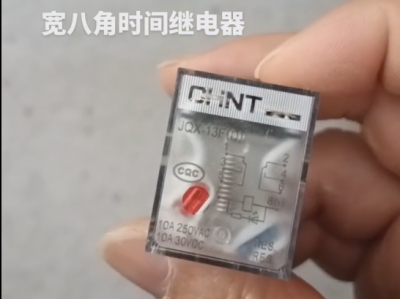
Chint JQX13F Electromagnetic Relay
-
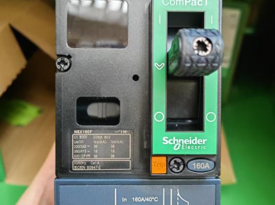
Schneider C16F2TM160 Circuit Breaker
-
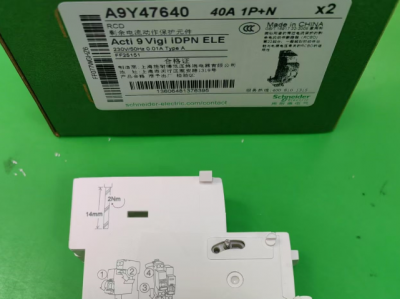
Schneider A9Y47640
-
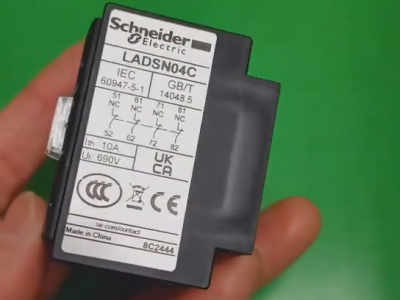
Schneider LADN04C
-
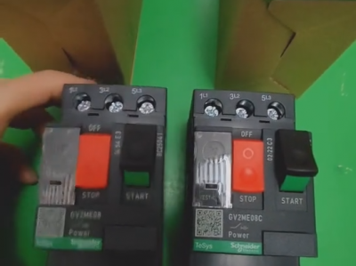
Schneider GV2ME08C motor circuit breaker
-
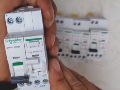
Schneider IDPNa C20A miniature circuit breaker (MCB)
-
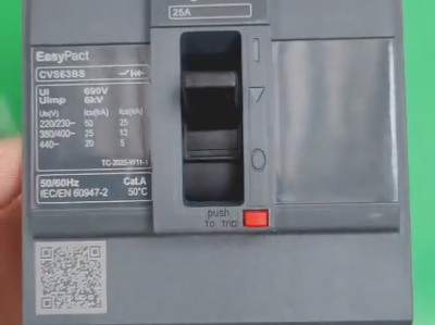
Schneider CVS63BS25A molded case circuit breaker (MCCB)
-
Schneider LC1DT80 4-pole contactors
-
Schneider Electric Circuit Breaker Model A9P28620

