
CHINT NS2-32H 17-23A AC motor starter
Product description
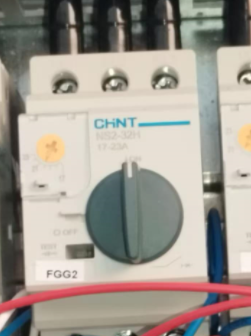
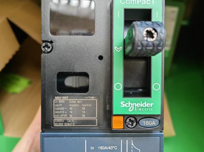
The following are the detailed technical parameters and application guidelines of the CHINT (CHNT) **NS2-32H 17-23A** AC motor starter, compiled by combining official documents and actual scenarios, covering key dimensions such as core functions, electrical performance, control characteristics, and compatibility:Schneider Circuit Breakers Price
I. Core Functions and PositioningChint's NB1-63DC series DC circuit breakers Price
The NS2-32H belongs to a **motor starter**, which is mainly used for **overload, phase failure, and short-circuit protection** of three-phase asynchronous motors and for infrequent starting control. It is suitable for scenarios such as industrial equipment, pumps, and fans. Its core features include:Chint NXR series thermal overload relays price
- **Setting current range of 17-23A**: It is suitable for motors with a power of approximately 3kW (needs to be adjusted according to the actual load).
- **Tripping characteristics**: It complies with the **10A class** of the IEC 60947-2 standard and is suitable for loads with high starting currents (such as fans and water pumps).CHINT contactor price
- **Integrated protection function**: There is no need for an additional thermal relay, simplifying the design of the control cabinet.
II. Electrical and Mechanical ParametersCHINT surge protector price
1. Electrical Performance
| Parameter | Value/Range | Explanation |
| Rated voltage | AC 230/240V, 400/415V, 440V, 500V, 690V | Supports wide voltage input and adapts to different power grid environments. |
| Rated current | 17-23A (setting range) | Can be adjusted by a knob or button to match the current on the motor nameplate. |
| Overload protection | Trips within ≤ 2 hours at 1.05 times the rated current, and trips within ≤ 2 minutes at 1.5 times the rated current | Complies with the 10A class tripping curve to protect the motor from long-term overload. |
| Short-circuit protection | Instantaneous tripping (10 times the rated current) | Fast response at the hardware level to protect the equipment from short-circuit damage. |
| Phase failure protection | Trips when the three-phase current imbalance is ≥ 50% | Prevents the motor from burning out due to single-phase operation. |
| Rated insulation voltage | 690V | Supports insulation reliability in high-voltage environments. |
2. Mechanical Specifications
- **Dimensions**: 120×100×80mm (H×W×D), suitable for installation on a standard 35mm rail.
- **Weight**: Approximately 0.8kg.
- **Protection level**: IP20 (needs to be installed in the control cabinet).
- **Installation methods**:Schneider LRD Thermal Relay Price
- **Front panel wiring**: Connect the main circuit through screws (recommended).
- **Plug-in installation**: Requires a special base (such as the CC series conversion connector, see).
III. Control and Interface Parameters
1. Control Functions
- **Manual/Automatic reset**:
- **Manual reset**: Press the reset button (RST) to restore after tripping.
- **Automatic reset**: Switch by adjusting the screw (manual reset by default, see).
- **Test function**: Supports simulated overload testing to verify the effectiveness of the protection function.
2. Interface Configuration
| Interface Type | Quantity/Specification | Purpose |
| Main circuit terminals | 3 poles (L1/L2/L3) | Connect the motor power supply wires. |
| Control circuit terminals | 2 (A1/A2) | Supply power to the coil (AC 230V/DC 24V optional). |
| Auxiliary contacts | 1NO + 1NC (needs to be purchased separately) | Status indication or interlocking control (such as fault signal output, see). |
IV. Environment and Certification
- **Operating temperature**: -5°C to +40°C (without derating), and a 20% derating is required from +40°C to +60°C.
- **Altitude**: No derating when ≤ 2000m, and derating is required when exceeding this altitude.
- **Certifications**:
- **Domestic**: CCC certification (see the certificate number).
- **International**: CE certification (complying with EN 60947-2), and some models support UL certification (the specific model needs to be confirmed).
V. Typical Applications and Configuration Examples
1. Motor Protection Scenarios
- **Fan control**:
- **Parameter setting**: Set the setting current = motor nameplate current × 1.1 (considering the starting impact).
- **Cooperating equipment**: Used in combination with CHINT NXC contactors (such as NXC-32), and simplify the wiring through the CC conversion connector (see).
- **Water pump control**:
- **Function activation**: Connect to the PLC through the auxiliary contacts to achieve fault alarm.
- **Special requirements**: If the water pump starts and stops frequently, it is recommended to select the automatic reset mode.
2. Matching with Frequency Converters
- **Compatibility**:
- **Current matching**: The output current of the frequency converter needs to be ≤ the setting current of the NS2-32H.
- **Harmonic processing**: If the frequency converter causes current distortion, the setting current needs to be increased by 1.3-1.9 times (see).
- **Installation suggestions**:
- **Position**: Install on the output side of the frequency converter, close to the motor.
- **Interference suppression**: Use twisted-pair wires to connect the control circuit to avoid high-frequency interference.
VI. Precautions and Selection Suggestions
1. **Selection Key Points**:
- **Current range**: Select according to the rated current of the motor (17-23A is suitable for a 3kW motor).
- **Tripping grade**: The 10A class is suitable for loads with long starting times (such as fans). If quick tripping is required, the 10 grade can be selected.
2. **Installation Requirements**:
- **Heat dissipation space**: Reserve a 50mm gap at the top/bottom to avoid the influence of high temperature on the protection accuracy.
- **Wiring torque**: Tighten the main circuit terminals to 4N·m to prevent poor contact.
3. **Fault Troubleshooting**:
- **False tripping**: Check the motor load, whether the wiring is loose, or reduce the starting current.
- **No tripping**: Test whether the protection function fails and replace the equipment if necessary.
VII. Accessories and Alternative Solutions
1. Optional Accessories
- **Auxiliary contact module**: AX-6 (1NO + 1NC), used for remote monitoring of the fault status.
- **Conversion connector**: CC-3(NS2), quickly connect the contactor and the starter (see).
- **Waterproof installation box**: Improve the protection level to IP55, suitable for humid environments.
2. Alternative Models
- **Upgrade solution**: If higher breaking capacity is required, the NS2-80H (80A, see) can be selected.
- **Economical choice**: NS2-32 (without auxiliary contacts), with a cost reduction of approximately 30%.
The overload protection action time of the CHINT NS2-32H 17-23A thermal overload relay strictly follows the **10A class tripping curve** of the IEC 60947-2 standard, and the matching of its core parameters with the actual application scenarios is as follows:
I. Core Parameters of the Overload Protection Action Time
According to the IEC 60947-2 standard and CHINT's official technical documents, the action time characteristics of the NS2-32H are as follows:
| Overload Multiple | Action Time Range | Typical Application Scenarios |
| 1.05 times | ≥ 2 hours without tripping | Long-term load fluctuations during normal motor operation |
| 1.2 times | ≤ 2 hours to trip | Light load overload (such as increased resistance caused by dust accumulation on the fan blades) |
| 1.5 times | ≤ 2 minutes to trip | Medium load overload (such as increased current after wear of the water pump impeller) |
| 6 times | ≤ 10 seconds to trip | Stalling or mechanical jamming (such as foreign matter blocking the conveyor belt) |
II. Dynamic Characteristics in Practical Applications
1. Inverse Time Characteristic
The action time of the NS2-32H has a **non-linear relationship** with the overload current, specifically manifested as:
- **The larger the overload multiple, the shorter the action time**. For example:
- When the current reaches **2 times the rated value** (34-46A), the action time is approximately **30 seconds**.
- When the current reaches **3 times the rated value** (51-69A), the action time is shortened to **10 seconds**.
- **Cold start characteristic**: When overloading starts from a cold state, the action time will be slightly longer than that in a hot state (after running for a certain period of time), and the specific difference is approximately **10-15%**.
2. Influence of Ambient Temperature
- **High-temperature environment** (such as +50°C): The action time may be shortened by **20-30%**, and the setting current needs to be appropriately reduced.
- **Low-temperature environment** (such as -5°C): The action time may be extended by **10-15%**, but it does not affect the effectiveness of the protection function.
3. Influence of Wiring and Installation
- **Too thin wires**: An increase in the resistance of the connecting wires will cause the action time to be advanced. It is recommended to use **multi-strand copper wires of 2.5mm² or above**.
- **Poor heat dissipation**: Insufficient installation spacing (such as the top/bottom gap < 50mm) will cause the action time to be shortened, and it is necessary to ensure good ventilation in the control cabinet.
III. Key Parameter Verification and Testing Methods
1. Manual Testing
- **Simulated overload**: Raise the current to **1.5 times the setting current** (25.5-34.5A) through an external voltage regulator, and observe whether the tripping time is ≤ 2 minutes.
- **Phase failure test**: Disconnect any one-phase power supply and verify whether the tripping time is ≤ **2 seconds** (phase failure protection characteristic).
2. Tool Verification
- **Clamp ammeter**: Record the overload current waveform in conjunction with an oscilloscope, and confirm that the deviation of the action time from the theoretical value is ≤ **±10%**.
- **Thermal relay tester**: Special equipment such as **CHNT-THR** is recommended, which can accurately simulate the action time under different overload multiples.
IV. Parameter Matching for Typical Application Scenarios
| Fault Phenomenon | Possible Cause | Solution |
| Frequent false tripping | The setting current is too low | Re-measure the actual current of the motor and adjust it. |
| No tripping under overload | Aging of the bimetallic strip | Replace the thermal overload relay. |
| No protection for phase failure | Fault in the phase failure detection circuit | Check the wiring of the auxiliary contacts or replace the module. |
V. Precautions and Selection Suggestions
1. **Cooperation with Contactors**:
- **Recommended model**: CHINT NXC-32 contactor (requires quick installation through the CC conversion connector).
- **Cooperation key points**: The breaking capacity of the contactor needs to be ≥ the starting current of the motor (usually 6-8 times the rated current).
2. **Alternative Solutions**:
- **Upgraded model**: If higher accuracy is required, the **NS2-32H + AX-6 auxiliary contact module** (supporting remote transmission of fault signals) can be selected.
- **Economical choice**: If short-circuit protection is not required, it can be replaced with the **NR2 series thermal relay** (with a cost reduction of approximately 40%).
VI. Typical Fault Troubleshooting
| Fault Phenomenon | Possible Cause | Solution |
| Frequent false tripping | The setting current is too low | Re-measure the actual current of the motor and adjust it. |
| No tripping under overload | Aging of the bimetallic strip | Replace the thermal overload relay. |
| No protection for phase failure | Fault in the phase failure detection circuit | Check the wiring of the auxiliary contacts or replace the module. |
More recommendations
-
Schneider LC1E400 Contactor
-
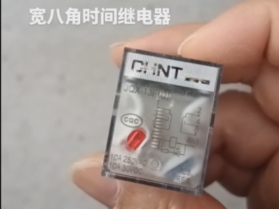
Chint JQX13F Electromagnetic Relay
-
Schneider C16F2TM160 Circuit Breaker
-

Schneider A9Y47640
-

Schneider LADN04C
-
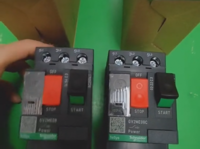
Schneider GV2ME08C motor circuit breaker
-
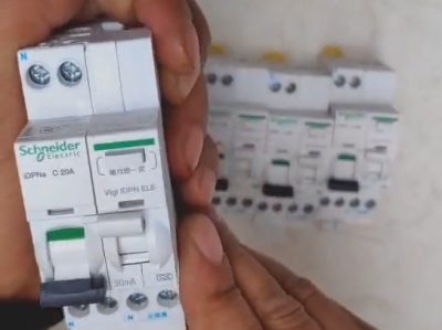
Schneider IDPNa C20A miniature circuit breaker (MCB)
-
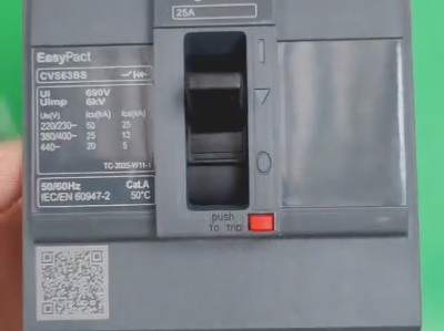
Schneider CVS63BS25A molded case circuit breaker (MCCB)
-
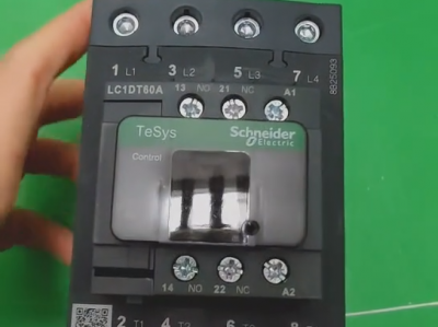
Schneider LC1DT80 4-pole contactors
-

Schneider Electric Circuit Breaker Model A9P28620

