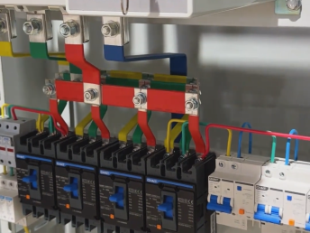
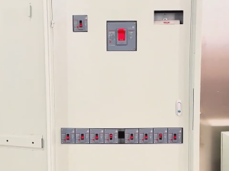
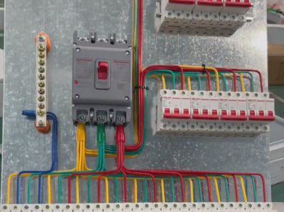
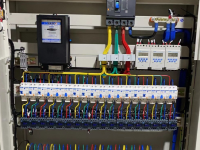
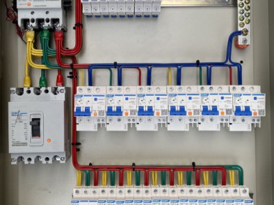
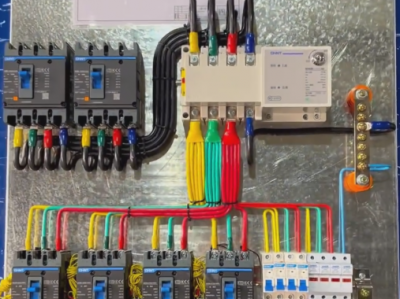
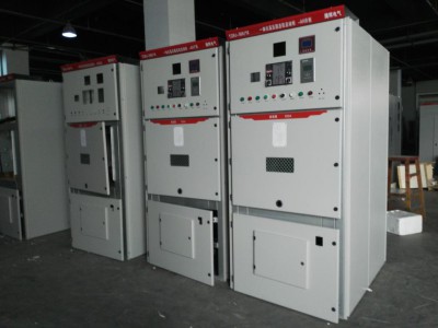
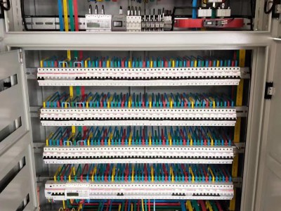
MNS low -voltage drawing switchgear
Product description
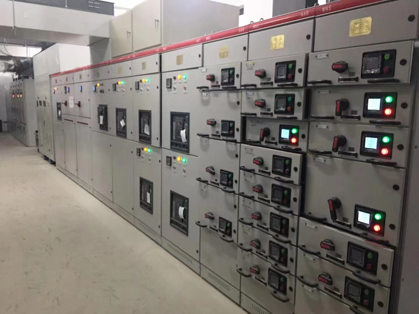 The MNS low -voltage complete set switchgear (hereinafter referred to aslow -voltage switchgear) is the development trend of universal control electrical combination of my country's low -voltage set switchgear. It has improved its electrical element and the switchgear structure, and registered. The electrical performance and mechanical performance of the product meet the technical requirements of the original MNS product.
This low-voltage switchgear is suitable for communication 50-60Hz, and the rated operating voltage of 660V and below. As a power generation, transmission, power distribution, and low-voltage switchgear to remove general land use, it can also be used for oil drilling at sea after special treatment. Platform and nuclear power plant. This low-voltage switchgear complies with the 5th part of IEC439 and VDE0660, GB7251-87 "Low-Voltage switchgear" standard and JB/T9661 "Low-voltage Dumping Terminal switchgear" industry standards.
Use environment
Surrounding air: temperature is not higher than+40 ° C, not less than -5 ° C. The average temperature within 24 hours must not exceed+35 ° C.
Applicable type: indoor
Altitude: 2000M
The relative humidity of the surrounding air: The maximum temperature is not more than 50%when the maximum temperature is+40 ° C. At the lower temperature, there is a large relative temperature: (for example, 90%when+20 ° C) allows at -25 ° C ~+50 ° C temperature temperature Transport and storage under conditions, and allow the temperature at 24H does not exceed+70 ° C;
Earthquake intensity: 9 degrees
Structural features
There are five standard -sized drawers with drawing MCC, which are 8E/4, 8E/2, 8E, 16E, and 24E. The structure of the two drawers of 8E/4 and 8E/2 is composed of flame retardant plastic and aluminum alloy materials (4 8E/4 or 2 8E/2 composition of an 8E height interval). The total height of the functional unit partition is 72E.
Five standard -sized drawers generally lead to 16 secondary isolation. If necessary, except for 8E/4 drawers, the other four drawers can be increased to 32. The connection line that does not have a quiet contact can be connected to 3 guide lines at the same time. The above -mentioned end is provided by the manufacturer with an appropriate amount of attachments and cold -rolled pliers with the product.
Through the operating program of the mechanical chain device, the drawer can be moved only when the main circuit auxiliary circuit is completely disconnected. The mechanical chain device makes the drawer a movement position, a break -off position and a separation position, and marked with the corresponding symbols. The operating handle on the mechanical chain device and the operating handle of the main section can be locked by three hanging locks at the same time.
Migratory electric motor control center and small current power distribution center (hereinafter referred to as migrant MCC)
Movement MCC's switchgear structure characteristics are the same as the same work in the same job (A) and (b)
The functional unit is designed as a migrant structure. The connection between the function unit and the vertical bus is an isolation contact. Even if the circuit connected to it is charged, the functional unit can be completely removed and returned to the function unit. The other end is a fixed structure.
The functional unit of the migrant MCC is 3E, 6E, 8E, 16E, 24E, 32E, and 40E functional unit partitions. The total height is also 72E.
Bus system
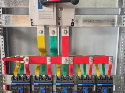
The horizontal bus (L1, L2, L3), the horizontal bus is installed in the independent bus partition behind the switchgear. It has two optional installation positions, namely 1/3 or 2/3 of the switchgear. The bus can be installed in the upper or lower part as required, or the upper and lower groups can be installed at the same time. The two groups of parent lines can be used separately or can be used in parallel. Each parent line is lined up in parallel by 2, 4 or 8 mothers, and 10*30*2, 10*60*2, 10*80*2, 10*60*4,10*80*2 and 10 *60*4*2 six.
The vertical bus is a L -shaped copper bus with 50*30*5. It is embedded in the function wall made of flame retardant plastic, and the protection level with the power part is IP20.
Neutral line (N line) and protecting ground line (PE line). The neutral line bus and protect the ground parallel are installed in the drooping of the functional unit partition in the cable room. If the N line and the PE line are separated from the insulator, the n line and the PE line are used separately. If the two are used to be short, the Penxg line is used as a Penxg line.
Protective grounding system
The protective circuit of this switchgear is composed of two parts: PE line (or PEN line) and conductive metal structures that are separated by the entire arrangement length. Except for the door and panels of the metal structure, the rest are galvanized. The structure of the structure is carefully designed to enable it to pass a certain short -circuit current.
Auxiliary circuit cable slot
The top of the function unit partition is equipped with auxiliary circuit cable grooves, and the connected lines and public power cords can be placed in the groove.

