
Wiring of Delixi AC Contactor
 Delixi AC contactors are commonly used electrical control devices. They can be used to frequently connect and disconnect AC and DC circuits and are widely applied in electric drive and automatic control systems. The following introduces common wiring methods for Delixi AC contactors.
Structure and Wiring Terminals of AC ContactorSchneider Circuit Breakers Price*
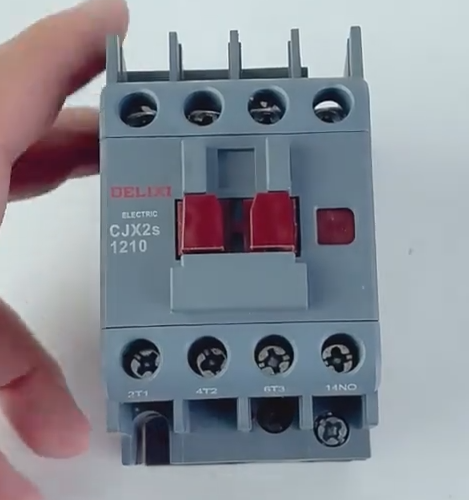
Delixi AC contactors are mainly composed of main contacts, auxiliary contacts, coils, etc. The common wiring terminals are as follows:
- **Main Contacts**: Generally, `L1`, `L2`, and `L3` represent the incoming terminals, while `T1`, `T2`, and `T3` represent the outgoing terminals. They are used to connect and disconnect the main circuit and can carry relatively large currents.
- **Auxiliary Contacts**: They are divided into normally - open contacts (NO) and normally - closed contacts (NC), which are used for signal transmission and interlock control in the control circuit.
- **Coil**: Usually represented by `A1` and `A2`. When the coil is energized, the main and auxiliary contacts of the contactor will act accordingly.
Common Wiring ExamplesChint's NB1-63DC series DC circuit breakers Price*
1. Wiring for Starting and Controlling a Single Motor
This is the most common application scenario, used to control the starting and stopping of a single motor.
- **Required Materials**: Delixi AC contactor, circuit breaker, thermal relay, start button, stop button, and motor.
- **Wiring Steps**:Chint NXR series thermal overload relays price*
1. **Power Incoming Line**: Connect the outgoing terminals of the circuit breaker to the incoming terminals `L1`, `L2`, and `L3` of the main contacts of the AC contactor.
2. **Main Circuit Connection**: Connect the outgoing terminals `T1`, `T2`, and `T3` of the main contacts of the AC contactor to the incoming terminals of the thermal relay, and connect the outgoing terminals of the thermal relay to the motor.
3. **Control Circuit Connection*CHINT contactor price*:
- Draw a control line from the outgoing terminal of the circuit breaker and connect it to one end of the stop button.
- Connect the other end of the stop button to one end of the start button, and connect the other end of the start button to one end `A1` of the coil of the AC contactor.
- Connect the normally - open auxiliary contact of the AC contactor in parallel with the start button to achieve a self - locking function.
- Connect the other end `A2` of the coil of the AC contactor to one end of the normally - closed contact of the thermal relay, and connect the other end of the normally - closed contact of the thermal relay to the other phase of the power supply.
2. Wiring for Forward and Reverse ControlCHINT surge protector price*:
It is used to control the forward and reverse rotation of the motor, usually requiring two AC contactors.
- **Required Materials**: Two Delixi AC contactors, circuit breaker, thermal relay, forward - rotation button, reverse - rotation button, stop button, and motor.
- **Wiring Steps**:
1. **Main Circuit Connection**: Connect the outgoing terminals of the circuit breaker to the incoming terminals of the main contacts of the two AC contactors respectively. After reversing the phase sequence of the outgoing terminals of the main contacts of the two AC contactors, connect them to the incoming terminals of the thermal relay, and connect the outgoing terminals of the thermal relay to the motor.
2. **Control Circuit Connection**:
- Draw a control line from the outgoing terminal of the circuit breaker and connect it to one end of the stop button.
- Connect the other end of the stop button to one end of the forward - rotation button and one end of the reverse - rotation button respectively.
- Connect the other end of the forward - rotation button to one end `A1` of the coil of the forward - rotation AC contactor. Connect the normally - open auxiliary contact of the forward - rotation AC contactor in parallel with the forward - rotation button. Meanwhile, connect the normally - closed auxiliary contact of the forward - rotation AC contactor in series in the control circuit of the coil of the reverse - rotation AC contactor.
- Connect the other end of the reverse - rotation button to one end `A1` of the coil of the reverse - rotation AC contactor. Connect the normally - open auxiliary contact of the reverse - rotation AC contactor in parallel with the reverse - rotation button. Meanwhile, connect the normally - closed auxiliary contact of the reverse - rotation AC contactor in series in the control circuit of the coil of the forward - rotation AC contactor.
- Connect the other end `A2` of the coils of both AC contactors to one end of the normally - closed contact of the thermal relay, and connect the other end of the normally - closed contact of the thermal relay to the other phase of the power supply.
Wiring Precautions
- **Safe Power - Off**: Be sure to turn off the power before wiring to prevent electric shock accidents.
- **Confirm Voltage**: Ensure that the rated voltage of the contactor coil is consistent with the power supply voltage of the control circuit.
- **Correct Wiring**: Wire strictly according to the wiring diagram and product manual to ensure correct connection of the main contacts, auxiliary contacts, and coils.
- **Tighten Terminals**: After wiring, check whether all wiring terminals are tightened to avoid poor contact caused by loosening.

