
6ES7142-5AF00-0BA0 Siemens
Product description
Regarding the Siemens **6ES7142-5AF00-0BA0** module, it is a **PROFIBUS DP interface module** (slave station) in the **ET 200SP distributed I/O system**, mainly used to connect the ET 200SP station to the PROFIBUS DP network and expand the input and output capabilities of the PLC. The following is the collation of its core information:
**I. Basic Product Information*Siemens 1FL6034-2AF21-1LH1 Servo Motor*
- **Model**: 6ES7142-5AF00-0BA0
- **Name**: ET 200SP PROFIBUS DP Interface Module (Slave Station)
- **Series**: SIMATIC ET 200SP
- **Functions*Siemens converter 6SE6440-2UD42-0GA1*:
- As a PROFIBUS DP slave station, it connects the ET 200SP distributed I/O station to the PROFIBUS network.
- Supports communication with the master station (such as S7-300/400, S7-1200/1500, etc.) and transmits input and output data.
- Can expand the I/O modules of ET 200SP (such as DI/DO, AI/AO, process modules, etc.).
*II. Technical Parameters*Siemens V20 Inverter 15KW of Model 6SL3210-5BE31-5UV0*
| Parameter | Description |
| Communication Interface | PROFIBUS DP (RS-485), supports baud rates from 9.6 kbps to 12 Mbps, conforms to the DP-V0 protocol. |
| Power Supply Voltage | DC 24V (powered by the power module PM-E or BU). |
| Maximum Number of Expandable Modules | Supports up to 32 I/O modules (depending on the power capacity and communication load). |
| Protection Level | IP20 (needs to be installed in the control cabinet). |
| Installation Method | DIN rail installation (35 mm), supports horizontal or vertical installation. |
| Configuration Tool | TIA Portal V13 and above, or STEP 7 V5.5 (requires installation of the GSD file). |
| Slave Station Address Setting | Manually set through the DIP switch on the module (1~126). |
*III. Wiring Method*Chint converters (NVF2G-18.5/TS4 or NVF2G-18.5/PS4*
*1. Power Supply Wiring**
- **Power Input**: Power the module through the **BU basic unit** or **PM-E power module**. The wiring is as follows:
- **L+**: Positive pole of DC 24V (connect to the positive pole of the power supply).
- **M**: Negative pole of DC 24V (connect to the negative pole of the power supply).
- **PE**: Ground terminal (needs to be reliably connected to the protective ground).
*2. PROFIBUS Communication Wiring*AB Inverter 25B-D043N114*
- **Interface**: 9-pin D-type plug (Sub-D) on the side of the module. The definition is as follows (facing the plug, pin 1 is at the top):
| Pin | Signal | Description |
| 1 | SHIELD | Shield layer (grounded) |
| 2 | M (GND) | Signal ground |
| 3 | RXD/TXD-P | PROFIBUS data positive (Line B) |
| 4 | n.c. | Not used |
| 5 | M (GND) | Signal ground |
| 6 | Vcc (5V) | 5V power supply (for active termination resistor) |
| 7 | P (Vcc) | Not used |
| 8 | RXD/TXD-N | PROFIBUS data negative (Line A) |
| 9 | n.c. | Not used |
- **Wiring Requirements**:
- Use a PROFIBUS dedicated cable (such as 6XV1830-0EH10). Connect Line A (green) to pin 8 and Line B (red) to pin 3.
- For the terminal stations, a termination resistor needs to be connected (the built-in termination resistor of the module can be enabled through the DIP switch, and the switch is located on the side of the module).
*3. Connection with I/O Modules**
- Physically connect the interface module with the I/O modules through the **BU basic unit of ET 200SP**. No additional wiring is required, and the modules communicate automatically through the backplane bus.
*IV. Configuration Steps (Taking TIA Portal as an Example)**
1. **Install the GSD File**: If using it for the first time, install the GSD file (support package) of ET 200SP in TIA Portal.
2. **Hardware Configuration**:
- Insert a "PROFIBUS DP" network in the project and set the master station parameters (such as address, baud rate).
- Find **6ES7142-5AF00-0BA0** in the hardware catalog, drag and drop it onto the PROFIBUS network, and set the slave station address (it needs to be consistent with the DIP setting of the module).
- Add the required I/O modules under the interface module and configure the input and output addresses.
3. **Download the Configuration**: Download the hardware configuration to the master station PLC to ensure normal communication.
*V. Application Scenarios**
- **Distributed Control**: Used in scenarios such as production lines, machine tools, and conveyor systems that require remote I/O expansion.
- **PROFIBUS Network Expansion**: As a slave station, connect to the PROFIBUS DP master station to expand the input and output points of the system.
- **Flexible Configuration**: Supports hot-swappable I/O modules, which is convenient for on-site maintenance and function expansion.
*VI. Precautions**
1. **Address Consistency**: The slave station address set by the DIP switch of the module must be consistent with the address in the configuration software.
2. **Termination Resistor**: For the first and last stations of the network, the termination resistor needs to be enabled (set the switch on the side of the module to "ON"), and for the intermediate stations, set it to "OFF".
3. **Power Supply Stability**: Ensure the stability of the DC 24V power supply to avoid module failures caused by voltage fluctuations.
4. **Reference to the Manual**: For specific wiring and configuration details, please refer to the official Siemens manual (《ET 200SP Interface Module Manual》).
For further operation guidance, it is recommended to visit the [Siemens Industrial Support Center] to download the product manual or contact technical support.
The technical parameters of this module are as follows:
| Parameter | Description |
| Communication Interface | PROFIBUS DP (RS - 485), supporting a baud rate of 9.6 kbps to 12 Mbps, conforming to the DP - V0 protocol. |
| Power Supply Voltage | DC 24V (powered by the power module PM - E or BU). |
| Maximum Number of Expandable Modules | Supports up to 32 I/O modules (depending on the power capacity and communication load). |
| Protection Level | IP20 (needs to be installed in the control cabinet). |
| Installation Method | DIN rail installation (35 mm), supporting horizontal or vertical installation. |
| Configuration Tool | TIA Portal V13 and above, or STEP 7 V5.5 (requiring the installation of the GSD file). |
| Slave Station Address Setting | Manually set through the DIP switch on the module (1 - 126). |
Previous:Wiring of Delixi AC Contactor
Next:The colors of wires in low-voltage distribution cabinets in various regions
More recommendations
-
Schneider LC1E400 Contactor
-
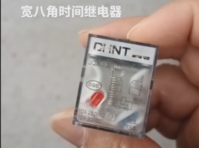
Chint JQX13F Electromagnetic Relay
-
Schneider C16F2TM160 Circuit Breaker
-
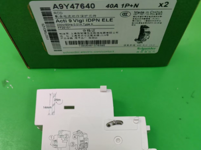
Schneider A9Y47640
-
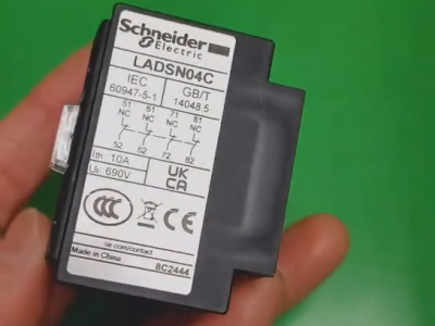
Schneider LADN04C
-
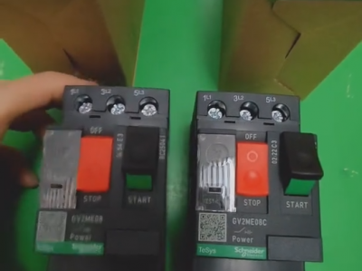
Schneider GV2ME08C motor circuit breaker
-
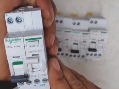
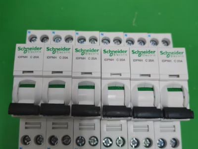
Schneider IDPNa C20A miniature circuit breaker (MCB)
-
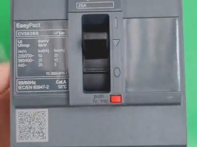
Schneider CVS63BS25A molded case circuit breaker (MCCB)
-
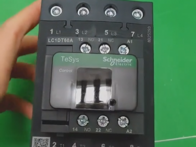
Schneider LC1DT80 4-pole contactors
-
Schneider Electric Circuit Breaker Model A9P28620

