
Chint NXC-75/220V AC contactor
Product description
 The Chint NXC-75/220V AC contactor is a commonly used industrial-grade control device suitable for controlling three-phase loads with a rated current of 75A and a coil voltage of 220V. Below is a detailed analysis of this contactor model:
*I. Basic Parameters and Specifications*Schneider LC1DN3210 and Chint NXC32 contactors*
1. **Rated Parameters*Chint DC Contactor NC1-5011-36V*
- **Model Meaning**: NXC-75 (design series)/220V (coil voltage)
- **Rated Current**: 75A (can control 37kW three-phase motors under AC-3 usage category)
- **Coil Voltage**: 220V AC (50/60Hz)
- **Pole Configuration**: 3 poles (main contacts) + 2 normally open (NO) + 2 normally closed (NC) auxiliary contacts
- **Mechanical Life**: 10 million operations
- **Electrical Life**: 1 million operations (AC-3 category)
2. **Application Scenarios*Wiring of Delixi AC Contactor*
- Start, stop, and forward/reverse control of three-phase motors
- On/off control of electric heating equipment and lighting circuits
- Combined with thermal relays to form motor protection circuits
*II. Core Structure and Terminal Description*CHINT AC contactor CJX2*
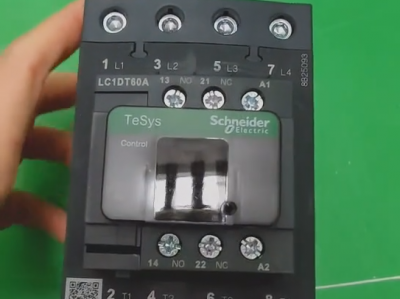
*1. Appearance and Components**

*(Schematic diagram; actual product may vary)*
*2. Terminal Layout**
| Terminal Type | Identification/Number | Function Description |
| Main Contacts | L1/T1, L2/T2, L3/T3 | Three-phase power input/output (L1-L3 for power supply, T1-T3 for load) |
| Coil Terminals | A1, A2 | 220V coil power supply (A1 to live wire, A2 to neutral wire) |
| Auxiliary Contacts | 13/14 (NO), 21/22 (NC) | Control circuit signal feedback (NO/NC) |
| Thermal Relay Interface | 95/96, 97/98 | Connect to thermal relay for overload protection |
*III. Typical Application Wiring Diagrams**
*Scenario 1: Direct Start Control of Three-Phase Motor**
```
┌─────────────────────────────────┐
│ Circuit Breaker (Q) │
│ ┌───┐ ┌───┐ │
│ L1 ──────┤ │───┤ ├───┬─────┘
│ │ │ │ │ │
│ L2 ──────┤ │───┤ ├───┼─────┐
│ └───┘ └───┘ │ │
│ │ │
│ ┌───┐ ┌───┐ │ │
│ L3 ──────┤ │───┤ ├───┴─────┘
│ └───┘ └───┘
│ │ │
│ ┌──────┴───────┴──────┐
│ │ Contactor Main Contacts │
│ │ (L1/T1-L3/T3) │
│ └──────┬───────┬──────┘
│ │ │
│ ┌───┐ ┌───┐
│ T1 ──────┤ │ │ │──── Motor U Phase
│ │ │ │ │
│ T2 ──────┤ │ │ │──── Motor V Phase
│ │ │ │ │
│ T3 ──────┤ │ │ │──── Motor W Phase
│ └───┘ └───┘
│
│ ┌───────────────┐
│ │ Control Circuit │
│ │ │
│ │ ┌───┐ ┌───┐ │
│ └──┤SB1├──┤KM ├──┘
│ │ │ │
└───┘ └───┘
Stop Coil A1
│
│
└───────────┐
│
│
┌───┐
│ │
│ │
└───┘
A2
│
│
└──── Neutral Wire N
```
**Explanation**:
- Circuit Breaker (Q): Protects the circuit from overloads and short circuits
- Contactor (KM): Main contacts control motor power supply; coil A1/A2 connected to 220V
- Start Button (SB1): When pressed, the coil is energized, main contacts close, and the motor starts
*Scenario 2: Motor Control with Overload Protection**
```
┌─────────────────────────────────┐
│ Circuit Breaker (Q) │
│ ┌───┐ ┌───┐ │
│ L1 ──────┤ │───┤ ├───┬─────┘
│ │ │ │ │ │
│ L2 ──────┤ │───┤ ├───┼─────┐
│ └───┘ └───┘ │ │
│ │ │
│ ┌───┐ ┌───┐ │ │
│ L3 ──────┤ │───┤ ├───┴─────┘
│ └───┘ └───┘
│ │ │
│ ┌──────┴───────┴──────┐
│ │ Contactor Main Contacts │
│ │ (L1/T1-L3/T3) │
│ └──────┬───────┬──────┘
│ │ │
│ ┌───┐ ┌───┐
│ T1 ──────┤ │ │ │──── Thermal Relay (FR)─┐
│ │ │ │ │ │
│ T2 ──────┤ │ │ │ │
│ │ │ │ │ │
│ T3 ──────┤ │ │ │ │
│ └───┘ └───┘ │
│ │
│ │
│ ┌──────────┴──────────┐
│ │ Motor │
│ └────────────────────┘
│
│ ┌──────────────────────────────────┐
│ │ Control Circuit │
│ │ │
│ │ ┌───┐ ┌───┐ ┌─────┐ ┌───┐ │
│ └──┤SB1├──┤SB2├──┤FR NC├──┤KM ├──┘
│ │ │ │ │ │ │ │
└───┘ └───┘ └─────┘ └───┘
Stop Start Overload Protection Coil A1
│
│
└───────────┐
│
│
┌───┐
│ │
│ │
└───┘
A2
│
│
└──── Neutral Wire N
```
**Explanation**:
- Thermal Relay (FR): Connected to the main circuit via terminals 95/96; NC contacts 97/98 are wired in series in the control circuit
- During overload, the bimetallic strip in FR heats and bends, opening the NC contacts, de-energizing the contactor coil, and stopping the motor
*IV. Installation and Usage Precautions**
1. **Environmental Requirements**
- Temperature Range: -5°C ~ +40°C
- Humidity: ≤95%RH (no condensation)
- Altitude: ≤2000 meters
2. **Installation Steps**
- Install vertically to maintain heat dissipation space
- Use M8 bolts for main circuit terminals, tightening torque 8-10N·m
- Use 0.75-2.5mm² wires for control circuits to ensure good contact
3. **Maintenance Key Points**
- Regularly clean oxide layers on contact surfaces
- Check for loose bolts (at least once a year)
- Coil temperature rise should not exceed 65K (at 40°C ambient temperature)
*V. Common Faults and Solutions**
| Fault Phenomenon | Possible Causes | Solutions |
| Coil not energizing | Power not connected, coil burned out, mechanical jamming | Check voltage, replace coil, clean components |
| Contact overheating | Poor contact, excessive load, contact oxidation | Tighten terminals, reduce load, polish contacts |
| Not releasing after power-off | Residual magnetism in core, contact adhesion | Replace core, clean or replace contacts |
| Excessive noise | Broken core short-circuit ring, voltage fluctuations | Replace core, stabilize power supply voltage |
*VI. Selection Alternatives**
If NXC-75 is out of stock, consider the following alternative models:
- **Schneider LC1-D75**: Same specifications, strong compatibility
- **Siemens 3TF52**: Higher reliability, suitable for critical applications
- **ABB A9-40/75**: Modular design, easy to expand
**Note**: When replacing, confirm that coil voltage, contact capacity, and installation dimensions are consistent.
Summary**
The Chint NXC-75/220V AC contactor is a reliable industrial control component that can effectively manage three-phase loads through proper wiring and maintenance. Before use, verify power supply compatibility and prioritize control circuits with overload protection to extend equipment life and ensure safety.
More recommendations
-
Schneider LC1E400 Contactor
-
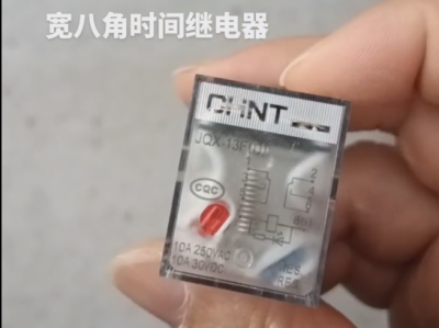
Chint JQX13F Electromagnetic Relay
-
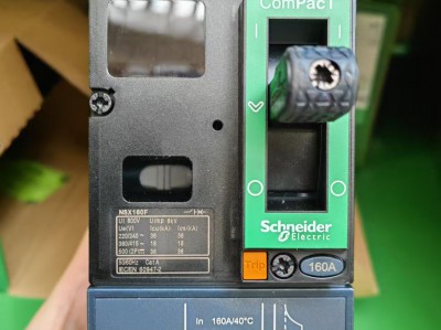
Schneider C16F2TM160 Circuit Breaker
-
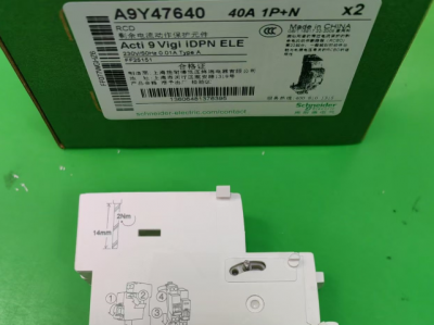
Schneider A9Y47640
-
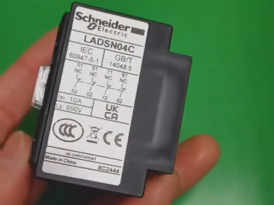
Schneider LADN04C
-
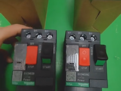
Schneider GV2ME08C motor circuit breaker
-
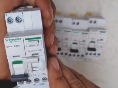
Schneider IDPNa C20A miniature circuit breaker (MCB)
-
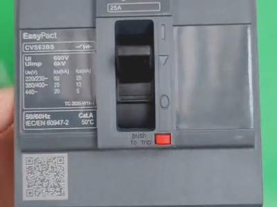
Schneider CVS63BS25A molded case circuit breaker (MCCB)
-
Schneider LC1DT80 4-pole contactors
-
Schneider Electric Circuit Breaker Model A9P28620

