
Siemens SINAMICS 6SL3210-1PB15-5UL0
Product description

The 6SL3210-1PB15-5UL0 is a power module of the Siemens SINAMICS G120 series. Below is its key information:
*Basic Parameters*Siemens 6SL3210-1KE18-8UF1*
- **Suitable Motor Power**:
- Heavy overload: 0.75 kW (200% overload for 3 s, 150% overload for 57 s, 100% overload for 240 s; ambient temperature: -10°C to +50°C).
- Light overload: 1.1 kW (150% overload for 3 s, 110% overload for 57 s, 100% overload for 240 s; ambient temperature: -10°C to +40°C). Siemens model number 6SL3210-1KE23-2UF1*
- **Power Supply Voltage**: 200–240 V ±10%, frequency 47–63 Hz, 1AC/3AC (single-phase input/three-phase output or three-phase input/three-phase output; specific descriptions may vary slightly due to data differences. Generally, three-phase input/output is the mainstream understanding. Here, the module supports three-phase input/output as a common scenario, and the broad description of 1AC/3AC in some materials covers input/output possibilities in different application scenarios, with three-phase being the primary application). Siemens S7-1200 series PLC*
- **Rated Current**: 6 A.
- **Protection Class**: IP20.
- **Dimensions*Siemens 6ES7253-1AA22-0XA0 (EM253)*
- Some data show 291x100x165 (height x width x depth) mm (FSB size).
- Other descriptions include 114.00x185.00x365.00 mm (differences may exist due to measurement methods or different versions; the former is used as the common description for the module's own dimensions, while the latter may include packaging or size definitions under different specifications).
- **Weight**: 2.9 KG.
*Product Features*Siemens 6ES7235-0KD22-0XA0*
- Belongs to the PM240-2 series, with no built-in filter and an integrated brake chopper.
- Control mode: integrated fieldbus; communication supports PROFINET-PN.
*Application Scope**
Suitable for industrial automation control, it can drive various types of motors and is commonly used in scenarios such as drive control for fans, pumps, compressors, etc. (specific applications need to be combined with actual system configurations and equipment requirements).
*Installation and Wiring Guide for Siemens 6SL3210-1PB15-5UL0 Power Module**
*I. Installation Guide* Siemens 6ES7231-5QA30-0XB0 module*
*1. Installation Environment Requirements**
- **Ambient Temperature**: -10°C to +50°C (light overload) or +40°C (heavy overload); derating is required above 40°C.
- **Humidity**: ≤95% relative humidity, no condensation.
- **Altitude**: ≤1000 m (derating is required for higher altitudes). 6ES7142-5AF00-0BA0 Siemens*
- **Protection Class**: Only suitable for control cabinets with IP20 protection.
- **Installation Position**: Install vertically, leaving at least 100 mm of heat dissipation space on all sides.
*2. Mechanical Installation Steps**
1. **Rail Mounting**: Fix the bottom slot of the module using a DIN rail (TS35/7.5 or TS35/15).
2. **Screw Fixing**: Tighten with M4 screws through the mounting holes on the top of the module (torque: 0.8–1.0 Nm).
3. **Module Arrangement**: When paralleling multiple units, the spacing between adjacent modules should be ≥25 mm (vertical direction) or ≥100 mm (horizontal direction).
*II. Wiring Methods**
*1. Power Supply Wiring (L1/L2/L3)**
- **Input Voltage**: 200–240 V AC, three-phase (or single-phase input; refer to the manual for details).
- **Cable Specification**: It is recommended to use 2.5–6 mm² stranded copper wires (selected according to the load current).
- **Wiring Steps**:
1. Remove the terminal cover (located on the front of the module).
2. Connect the power supply cables to the **L1, L2, L3** terminals (no polarity requirement).
3. Tighten the terminal screws (torque: 1.2–1.5 Nm).
*2. Motor Wiring (U/V/W)**
- **Cable Specification**: It is recommended to use 2.5–6 mm² stranded copper wires (needs to match the power supply cables).
- **Wiring Steps**:
1. Connect to the **U, V, W** terminals (corresponding to the three-phase windings of the motor).
2. Ensure the motor matches the module's power (0.75–1.1 kW).
*3. Brake Resistor Wiring (+/-)**
- **Brake Resistor Requirements**: An external brake resistor is required (recommended value: 200Ω/500W).
- **Wiring Steps**:
1. Connect the brake resistor to the **+** and **DB** terminals (the module has a built-in brake chopper).
2. If no braking function is needed, short-circuit the **+** and **DB** terminals.
*4. Control Circuit Wiring**
- **Digital Inputs (DI)**: 6 digital inputs (support PNP/NPN), default voltage 24V DC.
- **Analog Input (AI)**: 1 analog input (0–10V or 0–20mA, requires jumper settings).
- **Digital Outputs (DO)**: 2 relay outputs (rating: 2A/250V AC).
- **Analog Output (AO)**: 1 analog output (0–20mA).
- **Wiring Key Points**:
- Lay control cables separately from power cables to avoid interference.
- Use shielded cables with the shield grounded at one end.
*5. PROFINET Communication Wiring**
- **Interface**: Integrated RJ45 interface (X1).
- **Topology**: Supports linear, star, or ring topologies.
- **Wiring Steps**:
1. Use CAT5e or higher Ethernet cables to connect to a PLC or switch.
2. Termination resistor setting: Only activate the termination resistor for the last device in the network (set via a switch on the module).
*III. Safety Precautions**
1. **Power-Off Operation**: Disconnect the main power supply and wait for at least 5 minutes (for capacitor discharge) before wiring.
2. **Grounding Requirements**: The module's casing must be reliably grounded (ground resistance ≤10Ω).
3. **Polarity Check**: Ensure correct polarity for power supply and brake resistor wiring.
4. **EMC Compliance**: Use shielded power cables and follow Siemens' EMC installation guidelines.
*IV. Commissioning Recommendations**
1. **Parameter Setting**: Set basic parameters via STARTER or the SINAMICS G120C operation panel (e.g., P0003=3 to activate expert-level parameters).
2. **Motor Identification**: Perform quick commissioning (P0010=1) and automatic motor identification (P1910=1).
3. **Operation Test**: Run空载 (no-load) first, and only apply load after confirming correct direction and parameters.
For more detailed steps, refer to the Siemens official document **6SL3210-1PB15-5UL0 Operation Manual** (document number: A5E30077851).
More recommendations
-
Schneider LC1E400 Contactor
-

Chint JQX13F Electromagnetic Relay
-
Schneider C16F2TM160 Circuit Breaker
-
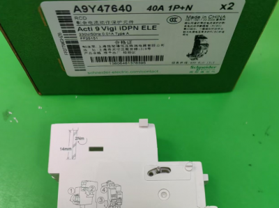
Schneider A9Y47640
-
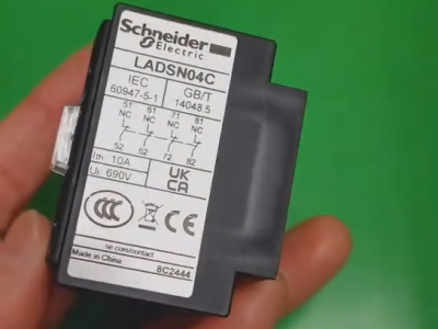
Schneider LADN04C
-
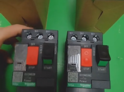
Schneider GV2ME08C motor circuit breaker
-
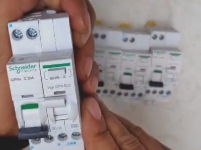
Schneider IDPNa C20A miniature circuit breaker (MCB)
-
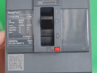
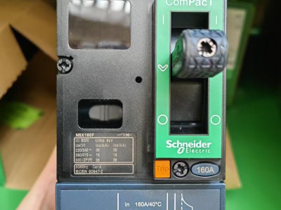
Schneider CVS63BS25A molded case circuit breaker (MCCB)
-
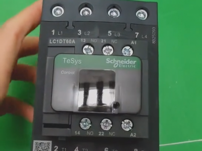
Schneider LC1DT80 4-pole contactors
-
Schneider Electric Circuit Breaker Model A9P28620

