
Siemens 6ES7253-1AA22-0XA0 (EM253)
Product description
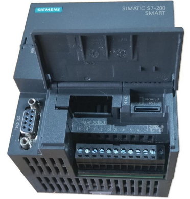
Siemens 6ES7253-1AA22-0XA0 (EM253) is a single-axis positioning expansion module specifically designed for the S7-200 series PLC. It is mainly used for the open-loop position control of stepper motors or servo drivers and supports a pulse output frequency of up to 200kHz. The following is a detailed analysis from aspects such as technical parameters, functional characteristics, installation configuration, application scenarios, and maintenance suggestions:Siemens 6ES7235-0KD22-0XA0
I. Core Technical Parameters
1. **Signal Types*Siemens 6ES7231-5QA30-0XB0 module*
- **Digital Inputs (DI)**: 5 channels, supporting functions such as STP (Emergency Stop), RPS (Reference Point Switching), LMT+ (Forward Limit), LMT- (Reverse Limit), and ZP (Origin Signal). The input delay (0.2~12.8ms) can be set through DIP switches.
- **Pulse Output (PTO)**: 2 differential signal channels (P0+/-、P1+/-), supporting RS422/RS485 or 5V DC output. The pulse frequency can reach up to 200kHz, which is used to control the direction and speed of the motor.
- **Control Outputs**: 2 channels (DIS, CLR), used for enabling the driver and clearing errors.
2. **Power Requirements*6ES7142-5AF00-0BA0 Siemens*
- **Module Power Supply**: 24V DC (independently supplied externally, with a maximum current of 130mA).
- **Backplane Bus**: 5V DC (provided by the CPU, with a maximum current of 190mA).
3. **Physical Characteristics*Siemens 1FL6034-2AF21-1LH1 Servo Motor*
- Dimensions: 71.2×80×62mm, with a weight of approximately 190g. It supports DIN rail installation or panel fixation.
4. **Certification and Compliance*Siemens converter 6SE6440-2UD42-0GA1*
- It complies with CE certification and supports the RoHS directive.
II. Functional Characteristics and Typical Applications
1. Core FunctionsSiemens V20 Inverter 15KW of Model 6SL3210-5BE31-5UV0
- **High-precision Positioning*Chint converters (NVF2G-18.5/TS4 or NVF2G-18.5/PS4*
- It supports motion modes such as absolute position, relative position, and homing. The motion envelope (such as speed, acceleration, and target position) can be defined through the "Position Control Wizard" in STEP 7-Micro/WIN.AB Inverter 25B-D043N114
- It has a built-in pitch compensation function to eliminate mechanical transmission errors.
- **Flexible Configuration*Siemens 6EP1 252-0AA01 chain power supply*
- The pulse equivalent (such as 0.01mm displacement corresponding to 1 pulse) and the electronic gear ratio (the transmission ratio between the motor and the load) can be set.
- It supports dynamically modifying parameters such as acceleration and deceleration time and maximum speed.
- **Safety Mechanism**
- The emergency stop input (STP) can immediately cut off the pulse output to protect the equipment.
- The limit switches (LMT+/-) and the origin signal (ZP) ensure that the mechanical stroke is within a safe range.
2. Typical Application Scenarios
- **Industrial Automation**
- Packaging machinery (such as material sorting, label pasting).
- CNC machine tools (such as tool positioning, worktable movement).
- **Logistics Equipment**
- Path control of automatic guided vehicles (AGVs).
- Precise positioning of storage shelves.
- **Experimental Equipment**
- Driving of stepper motors on laboratory platforms (such as spectrometers, pipettes).
III. Hardware Installation and Wiring Specifications
1. Module Connection
- **Communication with CPU**
- It is directly connected to the expansion slot on the right side of the CPU (such as CPU224, CPU226) through the expansion bus (flat cable) of the S7-200.
- The module address is automatically assigned according to the installation position (for example, the address of the first expansion module is 0).
- **Power Connection**
- The positive pole (L+) of the 24V DC power supply is connected to the `L+` terminal of the module, and the negative pole (M) is connected to the `M` terminal.
- Ensure that the power supply is independently supplied and avoid sharing the ground with the power supply of power equipment.
2. Signal Wiring
- **Stepper Motor Control**
- **Pulse Output**
- P0+/- is connected to the pulse signal of the driver (such as A+/-), and P1+/- is connected to the direction signal (such as B+/-).
- For differential signals, a twisted pair shielded wire should be used, and the shielding layer should be grounded at one end.
- **Limit and Origin Signals**
- LMT+/- is connected to the normally closed contacts of the limit switch, and ZP is connected to the normally open contact of the origin switch.
- The input signal should share the ground with the module (M terminal).
- **Servo Driver Control**
- If the driver supports the pulse + direction mode, the wiring method is the same as that of the stepper motor.
- If it supports analog quantity setting (such as a 0-10V speed command), an additional analog output module (such as EM253) needs to be connected.
3. Anti-interference Measures
- **Shielding and Grounding**
- A twisted pair shielded wire should be used for the signal cable, and the shielding layer should be grounded through the `PE` terminal of the module.
- Establish an equipotential body: Connect the metal frame of the control cabinet, the PE terminal of the module, and the grounding end of the motor through a copper busbar.
- **Wiring Specifications**
- The pulse signal wire should be laid separately from the power wire (with a spacing of > 30cm), and parallel routing should be avoided.
- For long-distance signals (> 50m), a signal isolator needs to be installed.
IV. Software Configuration and Programming Implementation
1. Hardware Configuration and Parameter Initialization
- **DIP Switch Settings**
- The input delay (for example, setting SW1-SW3 to `ON` to select 0.2ms) can be configured through the DIP switch on the side of the module.
- **Note**: The switch setting should be carried out after powering off, and the parameters of the entire module should be unified.
- **Position Control Wizard**
1. **Open the Wizard**: Select "Tools" → "Position Control Wizard" in STEP 7-Micro/WIN and select "Axis 0" (the default axis of EM253).
2. **Define Parameters**
- Pulse output mode (such as PTO), the number of pulses per motor revolution, and the electronic gear ratio.
- Motion envelope: Set the target position, speed, acceleration/deceleration.
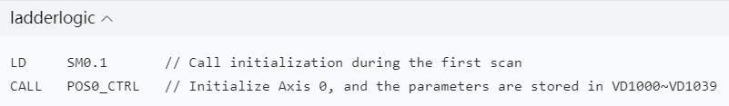
3. **Generate Function Blocks**: The wizard automatically generates subroutines (such as `POS0_CTRL`, `POS0_GOTO`) and data blocks (storing configuration parameters).
2. Programming Implementation
- **Initialization and Control Instructions**
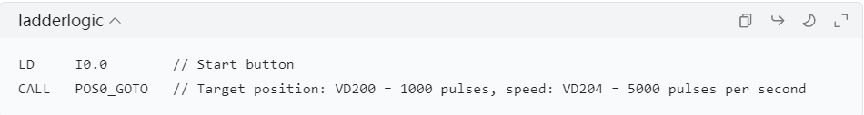
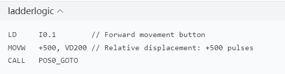
- **Absolute Positioning Example**
3. Function Testing and Calibration
- **No-load Test**
- Disconnect the motor and force the output of pulses through the programming software, and verify whether the signal is normal with an oscilloscope.
- **Load Test**
- Connect the motor, gradually adjust the speed and position, and observe whether the operation is smooth.
- **Origin Calibration**
- Perform the homing operation to ensure that the position value is 0 when the ZP signal is triggered.
V. Fault Troubleshooting and Maintenance Suggestions
1. Common Faults and Solutions
| Phenomenon | Possible Reasons | Solutions |
| The motor does not move | The pulse signal is not output, and the driver is not enabled | Check the program logic and the driver enable signal (DIS) |
| Large position deviation | Incorrect pulse equivalent setting, mechanical transmission clearance | Recalibrate the pulse equivalent and check the mechanical connection |
| The MF light is on (module fault) | Wiring error, signal out of range, or module hardware damage | Check the wiring, reset the DIP switch, and replace the module |
| Vibration or abnormal noise during movement | Too short acceleration and deceleration time, mismatched motor parameters | Increase the acceleration and deceleration time and confirm the motor parameters (such as current) |
2. Long-term Maintenance
- **Regular Inspection**
- Clean the dust on the surface of the module to ensure good heat dissipation.
- Check whether the wiring terminals are loose to avoid poor contact.
- **Data Backup**
- Export the configuration data block through Micro/WIN to prevent parameter loss.
- **Spare Parts Management**
- This module has been discontinued (discontinued in 2015). It is recommended to reserve spare parts or upgrade to the S7-1200 series.
VI. Alternative Solutions and Upgrade Suggestions
1. Direct Replacement
- **6ES7253-1AA22-0XA8 (CN version)**: It has exactly the same functions as the original model, supports the Chinese programming environment, and can be directly replaced.
2. Upgrade Replacement
- **S7-1200 Series Positioning Module (such as SM 1223)**
- It supports more axes (such as 4 axes) and higher resolution (16 bits), and is compatible with the TIA Portal programming environment.
- The CPU (such as CPU 1214C) and programming software need to be replaced, but it has stronger expandability.
- **S7-1500 Series CM 1242-5**
- It supports PROFINET communication and is suitable for complex motion control networks.
VII. Summary
The EM253 module is a core component for achieving precise positioning control in the S7-200 system. Its wiring and programming need to strictly follow the principles of "reliable hardware connection, accurate software configuration, and optimized environmental anti-interference". Through reasonable parameter settings and anti-interference measures, the stable operation of stepper motors or servo drivers can be ensured. For new projects or system upgrades, it is recommended to give priority to the S7-1200/1500 series to obtain higher performance and longer life cycle support. When purchasing, pay attention to the discontinued status of the module, select a reliable channel, and reserve testing time.
More recommendations
-
Schneider LC1E400 Contactor
-
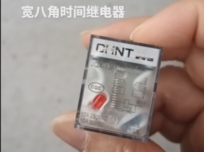
Chint JQX13F Electromagnetic Relay
-
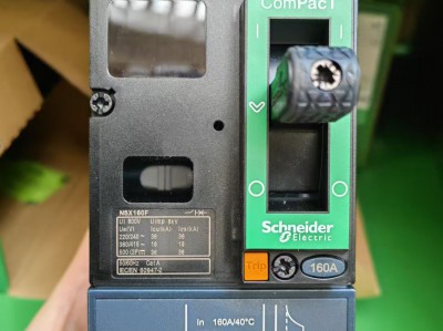
Schneider C16F2TM160 Circuit Breaker
-
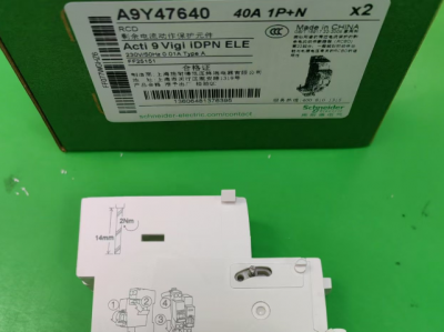
Schneider A9Y47640
-

Schneider LADN04C
-
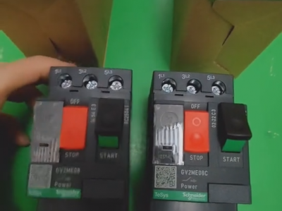
Schneider GV2ME08C motor circuit breaker
-
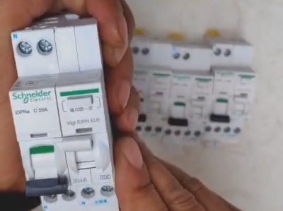
Schneider IDPNa C20A miniature circuit breaker (MCB)
-
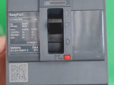
Schneider CVS63BS25A molded case circuit breaker (MCCB)
-
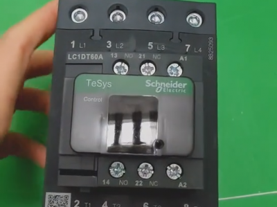
Schneider LC1DT80 4-pole contactors
-
Schneider Electric Circuit Breaker Model A9P28620

